
Practical Guide

Elcometer 121/4 Top P.I.G.: Reliably Test Coating Thickness & Cross-Hatch Adhesion
This guide provides a field-tested workflow for destructive coating thickness measurement with a 50x microscope – and (Top model) cross-hatch adhesion testing according to ISO/ASTM, including tool selection, reference values, troubleshooting, and maintenance.
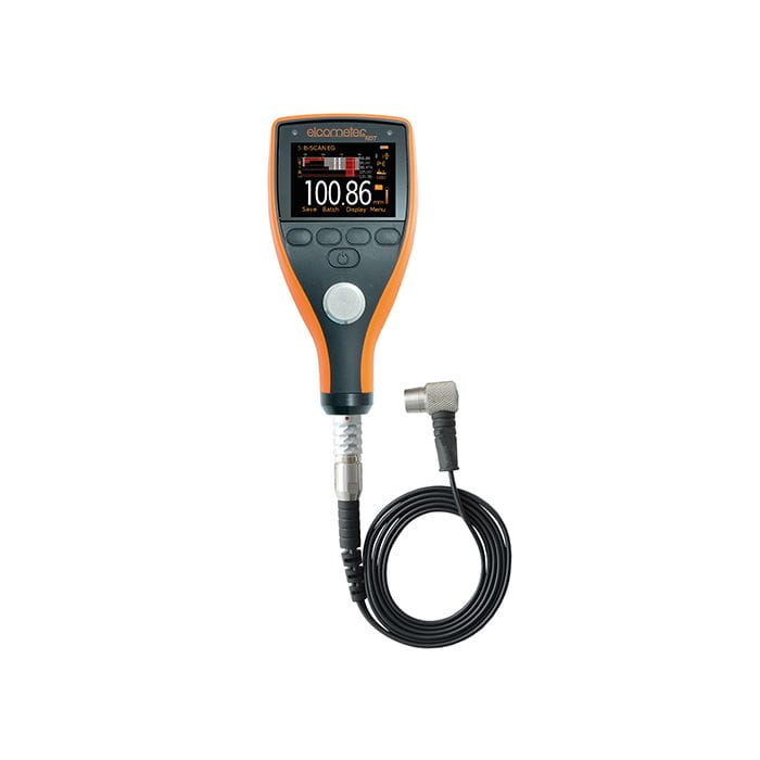
Note: Product image is for orientation purposes.
KPI 1
50x Microscope
Integrated microscope with rotatable scale – for fast reading directly at the cut edge.
KPI 2
3 Cutters in Device
Cutters #1, #4, #6 – quickly interchangeable via rotary dial on the Top model; optional cross-hatch tool available.
KPI 3
Two Test Types
Destructive thickness (cut) + (Top) Cross-hatch adhesion – ideal for quick workshop and site checks.
Pro Tip (Yellow Box): Contrast is Everything
Mark the measurement point before cutting so that the line provides a clear contrast to the coating. For dark coatings, a different pen color may be useful – this makes it easier to align the scale cleanly and reduces reading errors.
Product Overview: Variants, Usage & Benefits
| Variant | Suitable For? | What's Included? | Note |
|---|---|---|---|
| Top P.I.G. (A121---T) | Destructive thickness measurement + optional cross-hatch adhesion with additional tool | Cutters #1/#4/#6, 50x microscope, LED light, batteries, tool, marker, wrist strap, case, manual | Top model: switch quickly via internal tool holder |
| Top P.I.G. + Calibration Certificate (A121---TC) | As above – plus traceable cutter documentation per blade (depending on variant) | Same scope as Top P.I.G. + calibration option | Practical if you have internal/external documentation requirements |
Briefly explained: The Elcometer 121/4 is a handy testing device for coating thickness cut measurement and (Top) for cross-hatch adhesion tests with optional tools – particularly helpful in tight areas due to its compact design.
Recommended Basic Settings (Derived from manual – Guidelines)
The following values are guidelines and depend on factors such as coating, substrate, and standard specifications. For standardized tests, always follow the appropriate standard/work instruction.
| Application | Guideline / Selection | Why This Helps |
|---|---|---|
| Thickness: Cutter Selection | #6 for thin systems (fine cut angle), #4 as all-rounder, #1 for thick coatings (larger angle). | The correct angle ensures an easy-to-read cut width and reduces chipping. |
| Reading: Scale Factor | Per scale division: #1 ≈ 20 µm, #4 ≈ 10 µm, #6 ≈ 2 µm (metric scale). | Fast conversion from divisions to µm – consistently documentable. |
| Cross-hatch: Cut Length | Parallel cuts typically approx. 20 mm (guideline). | Results in a well-evaluable grid area without unnecessary large damage. |
| Cross-hatch: Tape Handling | Tape piece approx. 75 mm; pull off quickly according to procedure (e.g., ISO: within a few minutes; ASTM: within ~1–2 minutes – guidelines). | Time window and removal motion significantly influence reproducibility. |
Professional Workflow (5–7 Steps)
- Prepare Measurement Site: Clean the surface, define measurement points, and place contrast line with marker.
- Select Cutter: Choose #6/#4/#1 suitable for thin/standard/thick (guideline), insert tool correctly.
- Execute Cut: Place device so both guide wheels have contact; pull evenly with only as much pressure as necessary.
- Align Microscope: Activate lighting, sharpen focus, rotate scale perpendicular to the cut and align parallel to the cut edge.
- Read & Convert: Count scale divisions and convert to µm using scale factor or addition logic (guideline – depending on cutter).
- (Top) Supplement Cross-hatch: Select suitable cross-hatch cutter based on thickness/substrate, cut grid, de-dust, apply tape (if required), and perform evaluation.
- Document: Record values, cutter, position, coating structure (single/multi-layer), and cross-hatch class if applicable; repeat at multiple locations.
Troubleshooting (4 Typical Problems)
1) Cut edge appears frayed / "ragged"
- Check blade: Replace cutter if cuts are ragged.
- Reduce pressure and pull more evenly (do not "jerk").
- Consider substrate hardness: work with a clean, steady pull for very hard/brittle films.
2) Uncertain reading (edge/layer boundary difficult to see)
- Improve contrast line (different pen / better lighting).
- Ensure scale is rotated exactly perpendicular to the cut and aligned parallel.
- For clear lacquers on wood: potentially dye the exposed wood fiber to make the boundary visible.
3) Measured value appears too small (delamination/undermining is misleading)
- With poor adhesion, the coating may "break": always measure the correct distance along the cut geometry (do not follow the break).
- Take measurements at several points and calculate the average.
4) Cross-hatch results vary significantly
- Select cutter appropriate for coating thickness and substrate (hard/soft).
- Standardize tape/pull-off process (adhere to time window/pull angle guidelines per procedure).
- De-dust cleanly after cutting before evaluating.
Maintenance (5 Points)
- Replace cutter if cuts become ragged or reading quality suffers.
- Change LED batteries if light becomes weak or fails.
- Remove batteries during prolonged non-use (protection against leakage damage).
- (Top) Set tool holder to "Safe" position when not in use – reduces risk of injury.
- Do not attempt self-repairs: handle defects via service/manufacturer (observe warranty).
FAQ (Field Relevant)
1) How do I choose the right blade (#1/#4/#6)?
As a guideline: #6 for thin layers (finer), #4 as all-rounder, #1 for thicker layers. The key is that the cut width remains clean and easy to read.
2) Can I measure multi-layer systems?
Yes. You can measure the total thickness or (if the layers are clearly separable in the cut) read each layer individually and derive thicknesses from there.
3) When do I need the Top model?
If you want to test cross-hatch adhesion in addition to coating thickness or switch tools frequently: the Top model is designed for this (optional cross-hatch tool).
4) Cross-hatch or Pull-Off – which is "better"?
Cross-hatch is fast, inexpensive, and very practical for many coatings. If you need to document quantitative pull-off strength with a defined pull rate, an automatic pull-off device like the Elcometer 510 is an alternative (e.g., with selectable pull rates and data storage).
5) How do I prevent typical reading errors?
Set contrast lines cleanly, adjust focus correctly, align scale exactly (perpendicular/parallel), and test at least 3 measurement points per component/batch.
CTA: Order the Suitable Version Directly
Choose the variant that fits your documentation requirements – standard or with calibration option.
Conclusion
The Elcometer 121/4 Top P.I.G. is a powerful practical tool for quickly performing destructive coating thickness tests and (if needed) evaluating cross-hatch adhesion: clear handling, fast reading via scale factors, and a workflow-ready setup – ideal for workshops, quality assurance, and construction sites.