
Practical Guide

WIWA Pipe Coating: Internal Pipe Coating (50–800 mm) – Without Rotating the Pipe
In this guide, you will see how to select the right accessories (rotary atomizers, centering devices, lances, valves/regulators),
derive practical setup guidelines, and establish a clean workflow – including troubleshooting & maintenance checklist.
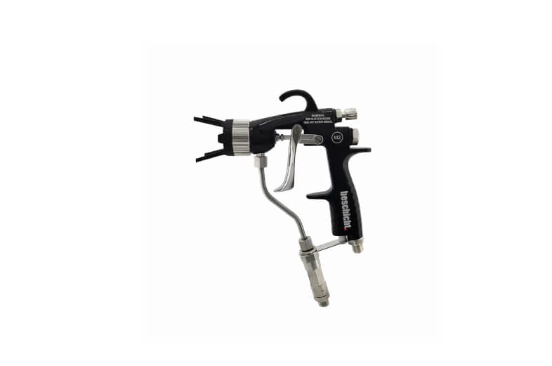
Note: Image is for orientation purposes (accessories/principle illustration).
Ø Range
50–800 mm
Internal coating of pipes via rotary atomizers/“spinning wheel” – without rotating the pipe.
Manual possible
up to 3 m
Hand-guided internal coating of pipes as well as bends/branches up to approx. 3 m length (guide value).
Centering
stable run
For Ø 50–100 mm, guidance is usually provided by two centering units; from Ø 100–400 mm (optionally up to 800 mm), adjustable centering solutions are available.
Why WIWA Pipe Coating Excels in Practice
- No pipe rotation necessary: Application occurs during the withdrawal of the movable lance.
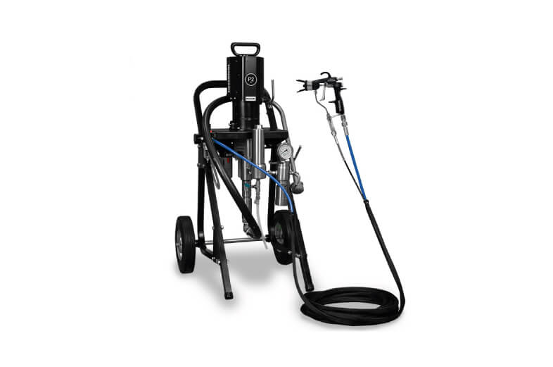
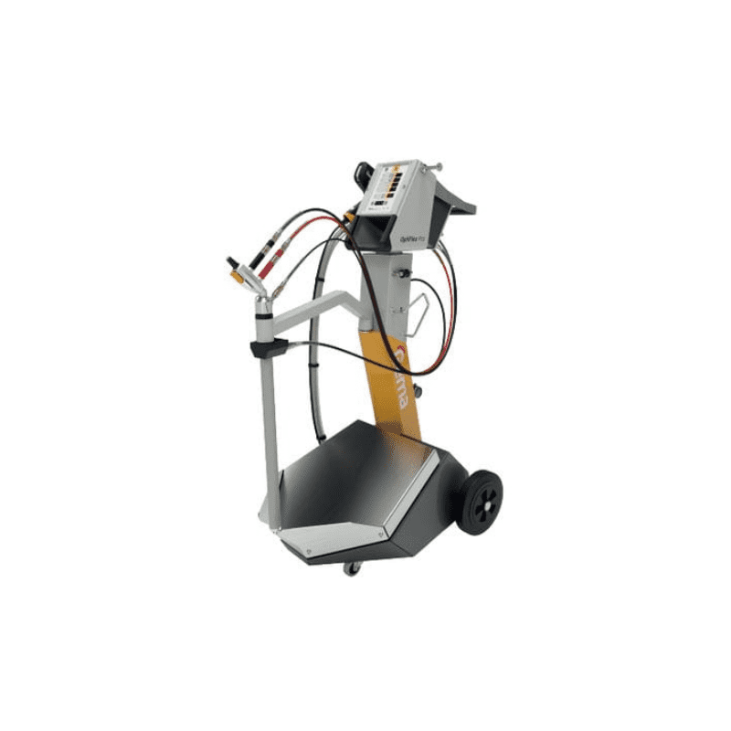
- Scalable: From manual lances to automated/robotic applications (depending on setup).
- Modular: Rotary atomizer wheels, centering devices, valve/regulator units, and lances are combined to match the diameter.
Product Overview: Accessories & Variants (from PDF/Manufacturer site)
| Component | Purpose? | Selection/Variant | Order No. (Examples) |
|---|---|---|---|
| Rotary atomizer wheel | Internal application via rotating wheel | Ø 33 / 45 / 90 mm | 0656957 / 0656958 / 0656959 |
| Automatic valve | Control/Switching in the system | for internal pipe coating | 0655976 |
| Centering guide | Guidance/Centering in the pipe | with rollers, e.g., 69–78.5 mm / 77.5–97 mm | 0657948 / 0657949 |
| Rings/Inserts (Ø) | Adaptation to smaller diameters | Ø 50 / 60 / 65 mm | 0658050 / 0658051 / 0658052 |
| Lance (motorized) | Drive/Handling in the pipe | Lance with motor, 600 mm | 0656960 |
| Hand lance with Gun | Manual application | Hand lance, 1800 mm | 0656948 |
| Guides for lance | Guidance depending on pipe Ø | Ø 100–400 / Ø 400–800 (for lance) | 0656954 / 0656956 |
| Conversion kit | Modification/Extension in the Ø range | Ø 400–800 (from Pos. 1 to Pos. 2) | 0649924 |
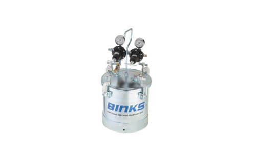
| Regulator unit | Regulator/Unit for mounting on the pump | incl. material & air hoses (system dependent) | 0655044 |
| PU 4040 Automatic Gun (Polyurea) | Automatic gun for internal pipe coating | Guide Ø 210–400 mm (larger Ø on request) | 0659289 |
Note: Order numbers/Ø ranges are taken from manufacturer documents; availability/set contents may vary depending on version/market.
Typical Applications
- Internal coating with automatic guns for manual or automatic spray lances.
- Internal coating of laid/“in-situ” pipes with robotics & rotary atomizers.
- Rotary atomizer systems for pipes larger than 50 mm diameter.
- Coating of bends/branches with rotary atomizers on a hand lance.
- Special equipment for sockets/joints in cast iron pipes (guide value: 80–800 mm).
Practical Tip: Centering first, “Spray Pattern” second
If the lance does not run cleanly centered, the spray pattern will appear "random" – even if material/air settings are correct.
Therefore, first adjust the appropriate guide (Ø-guide/roller guide) and check for smooth movement during insertion and withdrawal – only then fine-tune material and air flow at the regulator.
Recommended Basic Settings (derived as guidelines from PDF/Manufacturer logic)
The available documents primarily contain selection and system notes (Ø ranges, accessories, setup). Concrete pressure values are
material and pump dependent – therefore provided here as a guide value checklist instead of numbers:
- Determine Diameter: Measure pipe Ø (incl. tolerances/internal dimensions), then select appropriate guides/centering devices.
- Select Appropriate Rotary Wheel: Pre-select atomizer wheel (Ø 33/45/90 mm) according to pipe Ø and material viscosity (guideline).
- Assemble System Unit: Correctlly mount the regulator/unit including valve as well as material & air hoses to the pump.
- Withdrawal Application: Application occurs during the controlled withdrawal of the lance – keep speed constant (guideline).
- Test First, Then Series: Conduct a short trial run (smooth running? centering ok? uniform application?), then proceed to series production.
Pro Workflow (5–7 Steps)
- Inspect Component: Is the pipe interior clean/dry? Check edges, welds, transitions.
- Select Ø Setup: Mount appropriate guide/centering (usually two centering points for small Ø).
- Configure Atomizer & Lance: Select rotary wheel, mount lance (motorized or hand lance).
- Connect Regulator/Valve: Connect material and air lines according to system setup; check for leaks.
- Trial Run Without Material: Test insertion/withdrawal, verify centering and smooth running.
- Test Spraying: Short application in the pipe, then check result (coverage, uniformity, "runs").
- Series Application: Maintain constant withdrawal speed, re-test when Ø/geometry changes.
Troubleshooting: 4 Typical Problems
1) Irregular Application / Streaking
- Check centering: Is guide/roller guide suitable for the internal Ø?
- Stabilize withdrawal speed (do not "jerk").
- Check if rotary wheel is suitable for Ø/material (guide selection).
2) Lance "bumping" / not running smoothly
- Check guide position and roller travel, switch to adjustable centering if necessary.
- For Ø 50–100 mm: consistently use two centering points/guides.
- Check pipe internal contour (edges/welds) beforehand.
3) Material application too "thick" at pipe ends
- Do not slow down withdrawal at the end – maintain uniform motion until exit.
- Plan process so that start/stop points lie outside critical areas (if possible).
- Conduct a short test run and fine-tune parameters/handling.
4) Insufficient coverage in bends/branches
- Select hand lance/setup according to application for geometries (bends/branches).
- Adjust centering so that travel remains stable within the geometry.
- Test spraying on samples before starting series production.
Maintenance: 5 Points for Lasting Clean Results
- Keep rollers/centering guides clean, check for smooth operation (avoid deposits).
- Regularly check material and air lines for leaks & damage.
- Inspect rotary wheel/atomizer for wear and clean surface.
- Functional check of regulator/valve unit (switching/response behavior).
- After each use: carry out system-compliant cleaning/flushing according to material specifications.
Find Matching WIWA Pipe Coating Models Directly in the Shop
Choose the model that best fits your Ø range and application (manual/automated) – we are happy to support you with the design.
FAQ: Frequent Practical Questions
1) For which pipe diameters is WIWA Pipe Coating intended?
A range of approx. 50–800 mm is described for internal coating (depending on centering/setup).
2) Must the pipe be rotated during coating?
No – application is done via the rotary atomizer during controlled withdrawal of the lance from the pipe.
3) Why are two centering units often necessary for small Ø?
For approx. Ø 50–100 mm, guidance with two centering points is described to keep the run stable and avoid streaks/bumping.
4) Can I coat bends and branches?
Yes – bends/branches are mentioned as typical applications, e.g., with rotary atomizers on a hand lance (setup dependent).
5) Is there a solution for Polyurea in internal pipe coating?
The documents mention a "PU 4040 Automatic Gun for internal pipe coating with Polyurea" including guide instructions (further design depending on Ø upon request).
Conclusion
WIWA Pipe Coating is particularly strong when you stabilize the process consistently via Ø-matching centering, clean lance handling, and the appropriate rotary wheel selection.
Use this guide as a checklist – and then select the appropriate model in the shop to safely bring your internal pipe coating into series production.